104
%Vakuum kPa mbar Torr -kPa -mmHg -inHg
100 0 0 0 101,3 760 30
90 10 100 75 90 675 27
80 20 200 150 80 600 24
70 30 300 225 70 525 21
60 40 400 300 60 450 18
50 50 500 375 50 375 15
40 60 600 450 40 300 12
30 70 700 525 30 225 9
20 80 800 600 20 150 6
10 90 900 675 10 75 3
0 101,3 1013 760 0 0 0
B
A
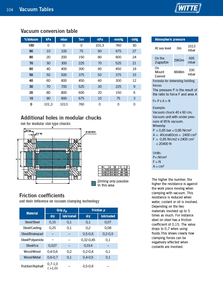
50 typ.
Ø 20/ M10
N r . A B C D
8 1 7 5 9 2 0 0 3 0 0 �� �� ������
8 2 8 3 7 3 0 0 4 0 0 ������ ������
8 2 8 2 5 4 0 0 6 0 0 ������ ������
in diesem Bereich kann gebohrt werden,
unter Berücksichtigung der Versorgungsbohrungen!
ø10 typ.
C
D
Drilling only possible
in this area
Vacuum Tables
Vacuum conversion table
Material
Grip μo Friction μ
dry lubricated dry lubricated
Steel/Steel 0,15 0,1 0,1 0,07
Steel/Casting 0,25 0,1 0,2 0,08
Steel/Brakepad – – 0,5-0,6 0,2-0,5
Steel/Polyamide – – 0,32-0,45 0,1
Steel/Ice 0,027 – 0,014 –
Wood/Wood 0,4-0,6 0,2 0,2-0,4 0,1
Wood/Metal 0,6-0,7 0,1 0,4-0,5 0,1
Rubber/Asphalt
0,7-1,0
( >1,0)
– 0,5-0,6 –
Atmospheric pressure
At sea level 0m
1013
mbar
On the
Zugspitze
2963m
695
mbar
On
Mount
Everest
8848m
330
mbar
Additional holes in modular chucks
not for modular slot type chucks
Friction coefficients
and their influence on vacuum clamping technology
Formula for determing holding
forces
The pressure P is the result of
the ratio to force F and area A
F= P x A = N
Example:
Vacuum chuck 40 x 60 cm;
Vacuum unit with under pressure
of 85% vacuum.
Whereby
P = 0,85 bar = 0,85 N/cm2
A = 40cmx60cm = 2400 cm2
F = 0,85 N/cm2 x 2400 cm2
= 20400 N
Units:
P= N/cm2
F = N
A = cm2
The higher the number, the
higher the resistance is against
the work piece moving when
clamping with vacuum. This
resistance is reduced when
water, coolant or oil is involved.
Depending on the two
materials involved up to 5
times as much. For instance
steel on steel has a friction
coefficient of 0,15. The value
drops to 0,7 when using
fluids.This shows clearly how
clamping forces can be
negatively affected when
coolants are involved.